
In the world of electrical control and automation, the contactor switch plays a crucial role in managing high-power circuits with low-voltage inputs. Whether in industrial settings, commercial complexes, or even modern smart homes, contactors ensure efficient and safe control of electrical loads. However, to ensure optimal performance and safety, correct wiring and configuration are essential.
This guide explores the fundamentals of contactor switch wiring and how proper configuration impacts system functionality. Additionally, we’ll discuss the role of the contactor relay, common wiring practices, and best practices for installation.
What is a Contactor Switch?
A contactor switch is an electrically controlled switch used for switching an electrical power circuit, similar in function to a relay but designed for higher current capacities. These devices are most commonly used to control electric motors, lighting systems, heating units, and other high-load electrical equipment.
Unlike manual switches, contactor switches operate automatically through a control signal, usually from a low-voltage circuit, making them an essential component in automated systems.
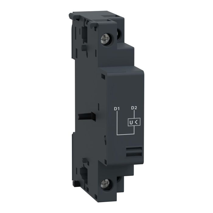
Understanding the Contactor Relay
A contactor relay is often used interchangeably with “contactor,” but technically, there is a distinction. While both are electromechanical switches, a contactor relay is generally used for lower current loads or for signaling tasks in control systems. It works in conjunction with contactor switches in multi-layered automation and control architectures, serving as the brain behind high-powered switching actions.
In many setups, the contactor relay acts as the control element, sending signals to the contactor switch to either complete or interrupt a power circuit.
Key Components of a Contactor Switch
To understand wiring and configuration, it’s important to be familiar with the key components of a contactor:
Coil (Electromagnet): Energized by a control circuit, this creates a magnetic field that pulls the contacts together.
Contacts: Includes main contacts for load connections and auxiliary contacts for control logic.
Enclosure: Provides safety and protection against dust, moisture, and accidental contact.
The main contacts handle the power circuit, while auxiliary contacts are used in control circuits to indicate status or implement interlocks.
Basics of Contactor Switch Wiring
Wiring a contactor switch correctly involves understanding both the power and control circuits. Here’s a step-by-step overview of typical contactor wiring:
Identify the Coil Terminals
Usually marked as A1 and A2, these terminals connect to the control voltage source (like 24V DC or 230V AC). When the coil is energized, it activates the contactor.
Connect the Power Supply to Line Terminals
The incoming power supply is connected to the L1, L2, and L3 terminals on the contactor. These are the terminals that receive the load voltage.
Connect the Load to the Output Terminals
The output side typically marked as T1, T2, and T3, is connected to the load, such as a motor or lighting system.
Use Auxiliary Contacts for Logic Control
Auxiliary contacts (NO – normally open, or NC – normally closed) can be used to send status signals or interlock with other devices.
Grounding and Safety
Ensure that the metal enclosure and exposed conductive parts are properly grounded to prevent electrical shocks or faults.
Important Wiring Considerations
Proper configuration and wiring of a contactor switch depend on various factors:
Voltage Compatibility
Ensure the coil voltage matches the control circuit voltage. Mismatched voltages can cause failure to operate or premature coil burnout.
Load Type
The contactor must be rated appropriately for the load type—be it resistive (like lighting), inductive (like motors), or capacitive (like power factor correction units).
Number of Poles
For three-phase applications, a three-pole contactor is standard. For single-phase or specific control tasks, a two-pole or four-pole contactor might be used.
Mechanical Interlocks
In systems where reverse motor rotation or multiple power sources are involved, mechanical interlocks prevent the simultaneous activation of opposing contactors.
Configuring the Contactor Relay for Smart Control
Modern systems often incorporate a contactor relay for more intelligent automation. This involves integrating relays into PLCs (Programmable Logic Controllers) or home automation hubs to execute complex tasks such as scheduled switching, overload detection, or remote control.
When configuring a contactor relay, consider:
Signal Input: Determine the input source that triggers the relay (manual switch, sensor, automation module).
Logic Programming: If used with a PLC, define the logic that determines when the relay energizes.
Interlocking Circuits: Use auxiliary contacts to ensure multiple contactors do not engage simultaneously if it could cause equipment damage.
Common Applications of Contactor Switches and Relays
The versatility of contactor switches and relays makes them suitable for various applications, including:
Motor Starters: Used in DOL (Direct-On-Line) and star-delta motor starting configurations.
HVAC Systems: To control compressors, fans, and thermostatic components.
Lighting Systems: For switching high-voltage lighting banks in commercial spaces.
Elevators and Escalators: For secure and responsive movement control.
Home Automation: When paired with smart systems, they can control appliances remotely.
Troubleshooting Contactor Switch Issues
If a contactor switch isn’t functioning correctly, the issue could be in the coil, contacts, or wiring:
No Response from Coil: Check the control voltage and verify coil resistance with a multimeter.
Contacts Not Closing/Open: Inspect for debris or worn-out contacts that might prevent proper operation.
Buzzing or Humming: This could indicate improper voltage or a partially energized coil—inspect wiring and source voltage.
Routine maintenance, such as tightening connections, inspecting for arc damage, and cleaning terminals, can greatly improve longevity and performance.
Safety Precautions During Installation
Working with contactors involves exposure to live electrical components. Always:
Isolate the Power: Ensure the system is de-energized before wiring or maintenance.
Use Insulated Tools: Prevent accidental contact with live parts.
Follow Manufacturer Guidelines: Refer to the datasheet or manual for voltage and current ratings.
Label Wires Clearly: To avoid confusion during future maintenance.
Conclusion
Understanding the essentials of contactor switch wiring and configuration is vital for setting up safe and efficient electrical systems, be it in homes, industries, or commercial spaces. By selecting the right contactor model, ensuring proper voltage matching, and integrating intelligent contactor relay logic, you can achieve seamless automation and protection.
For top-quality, durable, and reliable contactor switches and relays, explore the extensive product range available at Schneider Electric eShop. Backed by industry-leading technology and trusted engineering, Schneider Electric ensures your control systems perform at their best—safely and efficiently.